Search filter
Filter
Reset- Installation drawing (887)
- Product data sheet (848)
- Installation instructions (358)
- Tender texts (294)
- 3D model (181)
- Product scale drawing (147)
- Certificate (114)
- Declarations of performance (91)
- Cable plan (76)
- Declaration of conformity (72)
- Wiring diagram (43)
- Product declaration (LEED, DGNB, EPD) (43)
- User manual (33)
- Supplementary sheet (25)
- Flyer/folder (24)
- Product brochure (22)
- Type examination certificate (9)
- T&C / Data Protection (8)
- Software (5)
- Supplier information (4)
- Customer information (3)
- Installation situation (2)
- Safety analysis (2)
- Evaluation/comment (2)
3293 results found
General terms of use for the supplier portal
General Conditions of Use for the GEZE GmbH Supplier Portal 1. General Information … . GEZE GmbH (hereinafter referred to as GEZE) operates a supplier portal on the internet site https://www.geze-partnerlogin.de for electronic cooperation with partners. Use of the supplier portal takes place exclusively on the basis of these general conditions of use (hereinafter referred to as conditions of use). … . The access protected area of the supplier portal provides functions, applications and information with which business processes between GEZE and its partners are illustrated. A right to supplier portal registration does not exist. … . The aim of the supplier portal is to obtain more information on requirements and to plan internal activities for both partners. The supplier portal informs the partner about the requirements at GEZE. It supports him in achieving the best possible commitment to deadlines. The delivery dates are generally illustrated on a daily basis and should be understood as the date on which the confirmed delivery should be received by GEZE. The joint aim is to strictly adhere to confirmed delivery dates. … . The basis for processing further business between GEZE and the partner is formed by individual contractual agreements as well as GEZE's general terms of purchasing and delivery, which can be downloaded at www.geze.com/geze-portals. 2. Supplier Portal Registration … . In order to allow the partner access to the supplier portal, he is given an individual user ID as well as a password, which must be kept secret. The partner is obliged to impose the necessary care and confidentiality in handling this information on employees. He must ensure that unauthorised third parties do not gain knowledge of his individual access data. … . GEZE is entitled to remove registered partners from the supplier portal at any time without providing a reason and to block access. 3. Use of the Supplier Portal … . Use of the supplier portal by the partner is free of charge. The partner provides the necessary hardware. He also covers the costs for the connection. … . Use of the supplier portal is only for the purposes of business relationships between the partners. GEZE is entitled to specify or change the period and scope of access authorisations to the supplier portal at any time. … . The user is obliged to refrain from all activities that could lead to destruction or manipulation of GEZE's data records or IT systems by the user or a third party. 4. Processing … . The partner will confirm the orders issued by GEZE via the supplier portal if he accepts the specifications and conditions stated in the order. … . The partner will print out the delivery notes via the supplier portal and enclose them with the order. … . GEZE automatically processes all data registered by the partner in the supplier portal in digital form. The partner is therefore responsible for the reliability and accuracy of the data. … . The partner must make sure that the receipt of e-mails under the stated e-mail address is possible. He must therefore particularly ensure that the stated contact data is always up-to-date. 5. Copyrights … . The contents of the supplier portal are the property of GEZE and are copyright protected. They may not be copied, distributed, changed or made accessible to third parties without consent. … . Texts, images, graphs and drawings are subject to copyright protection and other protection rights. The copyrights, name and brand rights as well as GEZE's protection rights, especially the brand name and logos, must be observed. All types of documents provided by GEZE via the supplier portal remain the property of GEZE and may not be used and/or reproduced for purposes other than the contractual purposes. 6. Confidentiality … Both sides agree to treat all commercial or technical details they become aware of due to the business relationship and use of the supplier portal as trade secrets. … . The partner will obligate his employees and third parties to maintain confidentiality. The partner will immediately notify GEZE if he notices that his access data and/or information to be kept secret is obtained by an unauthorised third party or if confidential documents have gone missing. … . GEZE reserves the right to take legal action in the event of a violation against these regulations, especially the misuse of specific partner access data. … . The confidentiality obligation also applies after the end of the business relationship and is only void if the information received has been generally disclosed. General Conditions of Use for the GEZE GmbH Supplier Portal Version: December 2013 Page … of … 7. Liability and Data Protection … . If GEZE provides information via the supplier portal, the information has been carefully compiled by GEZE. Furthermore, GEZE is not liable for the availability or functionality of the supplier portal. The provided information is without obligation and is subject to possible amendment at any time. … . GEZE observes the applicable laws on data protection and data security when using and processing personal data. 8. Final Clauses … . GEZE reserves the right to change these conditions of use at any time. Appropriate reference will be made to changes. … . German law applies to contractual relationships under exclusion of the convention on contracts covered by the United Nations Convention on Contracts for the International Sale of Goods (CISG) from … .1980. … . Should one or more of the above provisions be or become ineffective or infeasible, this shall have no effect on the validity of the other provisions. The effective and feasible provision that comes as close as possible to the economic purpose of these general terms of purchase takes the place of the ineffective or infeasible provision. This applies correspondingly to regulation loopholes. … . The exclusive court of jurisdiction for any disputes resulting from or in association with these conditions of use is Stuttgart. General Conditions of Use for the GEZE GmbH Supplier Portal Version: December 2013 Page … of 2
PDF | 30 KB
Supplier self-information
DOCUMENT | 365 KB
Powerturn opening restrictor
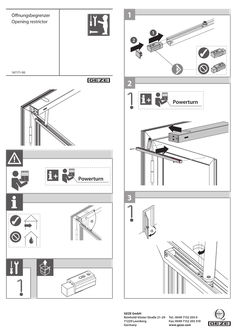
1 Öffnungsbegrenzer Öffnungsbegrenzung Opening restrictor … 2 156338-00 167171-00 … + + Powerturn Powerturn … α α GEZE GmbH Reinhold-Vöster-Straße 21–29 71229 Leonberg Germany Tel.: 0049 7152 203 … Fax: 0049 7152 203 310 www.geze.com
PDF | 2 MB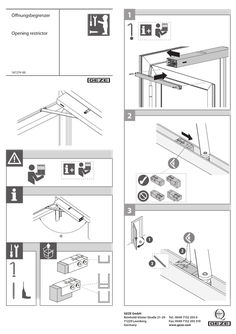
Opening restrictor
1 Öffnungsbegrenzer Öffnungsbegrenzung Opening restrictor + Opening restrictor 156338-00 167274-00 … + … α α … 2 … GEZE GmbH Reinhold-Vöster-Straße 21–29 71229 Leonberg Germany Tel.: 0049 7152 203 … Fax: 0049 7152 203 310 www.geze.com … 7 Ø … 5 M5 … mm … Nm … 9 … Ø …
PDF | 2 MB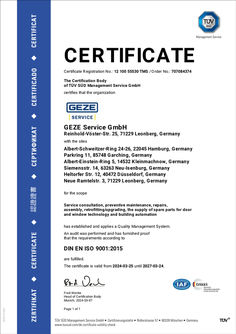
TÜV certificate Quality Management System ISO 9001 GEZE Service GmbH
CERTIFICATE Certificate Registration No.: 12 100 55530 TMS / Order No.: 707084374 The Certification Body of TÜV SÜD Management Service GmbH certifies that the organization GEZE Service GmbH Reinhold-Vöster-Str. 25, 71229 Leonberg, Germany with the sites Albert-Schweitzer-Ring 24-26, 22045 Hamburg, Germany Parkring 11, 85748 Garching, Germany Albert-Einstein-Ring 5, 14532 Kleinmachnow, Germany Siemensstr. 14, 63263 Neu-Isenburg, Germany Heltorfer Str. 12, 40472 Düsseldorf, Germany Neue Ramtelstr. 3, 71229 Leonberg, Germany for the scope Service consultation, preventive maintenance, repairs, assembly, retrofitting/upgrading, the supply of spare parts for door and window technology and building automation has established and applies a Quality Management System. An audit was performed and has furnished proof that the requirements according to DIN EN ISO 9001:2015 are fulfilled. The certificate is valid from 2024-03-25 until 2027-03-24. Fred Wenke Head of Certification Body Munich, 2024-03-07 Page … of 1
PDF | 172 KB
TÜV certificate Quality Management System ISO 9001 GEZE GmbH
CERTIFICATE Certificate Registration No.: 12 100 55459 TMS / Order No.: 707084360 The Certification Body of TÜV SÜD Management Service GmbH certifies that the organization GEZE GmbH Reinhold-Vöster-Str. 21-29 71229 Leonberg Germany for the scope Development, production and distribution of mechanical and automatic drive systems for doors and windows, emergency exits, access control systems, smoke and heat exhaust systems including the sites see enclosure has established and applies a Quality Management System. An audit was performed and has furnished proof that the requirements according to DIN EN ISO 9001:2015 are fulfilled. The certificate is valid from 2024-03-25 until 2027-03-24. Fred Wenke Head of Certification Body Munich, 2024-03-25 Page … of … ENCLOSURE OF CERTIFICATE Certificate Registration No.: 12 100 55459 TMS / Order No.: 707084360 certificate holder: GEZE GmbH Reinhold-Vöster-Str. 21-29 71229 Leonberg Germany at the sites scope GEZE GmbH Reinhold-Vöster-Str. 21-29 71229 Leonberg Germany Central functions for the management system, Development, production and distribution of mechanical and automatic drive systems for doors and windows, emergency exits, access control systems, smoke and heat exhaust systems GEZE d.o.o Elemirski put … 23000 Zrenjanin Serbia Production of mechanical and automatic drive systems for doors and windows, emergency exits, access control systems, smoke and heat exhaust systems EDORA OTOMATİK KAPI SİSTEMLERİ SANAYİ VE TİCARET ANONİM ŞİRKETİ ASO 2.OSB ALCI MAH. 2014 CADDE NO:31 SİNCAN 06930 Ankara Turkey Manufacture, development, marketing, sales and technical service of automatic doors Fred Wenke Head of Certification Body Munich, 2024-03-25 Page … of 2
PDF | 254 KB
Supplementary sheet GC 175 wireless input module
… Technical data Wireless input module GC 175 comprising: ID 163068 Wireless input module GC 175 Main battery and slave battery Resistor … kΩ Battery set (spare) ID 163228 ID 163229 Type CR 123A (3 V DC) Type CR 2032A (3 V DC) Matt black 52 mm x 32 mm 130 mm Termination resistor … kΩ at the end of the line Signals the state of an external potential-free contact (N/O contact) to the wireless module GC 171, monitors the line to the contact for breaks Installation in flush-mounted socket or cavity box. Installation in such a way that removing the wireless module and manual trigger switch is only possible after these two assemblies have been disconnected from one another (e.g. installation of the two assemblies in two different flush-mounted sockets). Spare resistor Main battery Slave battery Colour Dimensions (dia. x H) Line length Cable length Line monitoring Functional principle GC 175 EN Supplementary sheet Wireless input module Installation position 183157-01 … Brief description of wireless kit The wireless kit is part of the GEZE hold-open system FA GC 150 or FA GC 160. The wireless module GC 171, ID 163051, makes wireless communication possible between the lintel-mounted smoke switch and the various wireless devices. àà Wireless ceiling-mounted smoke detector GC 172, ID 159656 àà Wireless ceiling-mounted thermal detector GC 173, ID 159657 àà Wireless input module GC 175, ID 163068 (for the connection of manual trigger switches or contacts for the fire detector system) … Wireless input module GC 175 … Use IP rating (in acc. with EN 60529) Ambient temperature Service life main battery Signal transfer period Antenna Frequency range Range Quantity Modulation technique Radiated power … ON Potential-free contact … 4 … 7 … Housing Antenna Antenna socket Set-up switch … 6 … 8 CR2032 LED for displaying state Main battery Slave battery Housing tab Connection of a potential-free contact to the wireless input module GC 175 àà Installation in such a way that removing the wireless input module and manual trigger switch is only possible after these two assemblies have been disconnected from one another (e.g. installation of the two assemblies in two different flush-mounted sockets). àà Connect the potential-free contact as a N/O contact. àà Several contacts are connected in parallel. àà A … kΩ resistor is connected in parallel to the last contact. … CR123A Component at risk from electrostatic charge Do not touch the antenna! Use cable type J-Y(ST)Y, 2x0.6 mm or 2x0.8 mm. Length max. … m. 60 s integrated … MHz to … MHz 10 m (100 m in space) Frequency channels … FSK (frequency shift keying) … dBm (3 mW) … 1 … 3 … -5°C to 50°C … years … A wireless module GC 171 is essential for use of the wireless input module GC 175. Heed the document for the hold-open system FA GC 150 or FA GC 160 - Instructions for the installation, commissioning, operation and maintenance, see www.geze.com. IP20, only for dry areas … The GC 175 is a wireless input module for use in the GEZE hold-open system FA GC 150 or FA GC 160. Signal transfer from the wireless input module takes place wirelessly. The wireless input module monitors the switching state of a N/O contact and sends this per wireless signal to a wireless module GC 171. The N/O contact can be the contact of a manual trigger switch or the contact of a fire detector system. CAUTION Potential-free contact Signalling State, event LED for displaying state Switch on after removal of the insulation film or after the main battery has been inserted Start set-up of the wireless connection Fault during set-up of the wireless connection Operation Broken cable Main battery discharged Slave battery discharged Main and slave batteries discharged Other faults Contact closed, short-circuit flashes 10 x green, then red briefly, then the LED is off flashes … x green, … x yellow, … x red red off off flashes yellow ( … s on – … s off) flashes green ( … s on – … s off) flashes yellow/green alternately ( … s on – … s off) flashes yellow/green alternately ( … s off each) flashes … x red Battery replacement The wireless detector signals “Low battery charge” to the wireless module GC 171 if the charge state of the batteries is no longer sufficient. Both batteries (main battery and slave battery) always have to be replaced together. The set-up switch for the wireless detector must not be activated. XX 1. Bend the tabs on the side of the bottom part of the housing open slightly and pull the top part of the housing up and off carefully (the antenna will be pulled out of the antenna socket at this point). XX 2. Remove the main battery. XX 3. Use a small screwdriver to carefully remove the slave battery. XX Ensure that the PCB does not become damaged. XX 4. Slide the new slave battery (type CR2032A) into place – the positive pole faces upwards. XX 5. Insert the new main battery (type CR123A) – make sure polarity is correct. XX 6. Replace the top part of the housing carefully, making sure the antenna meets the antenna socket. XX 7. Replace the top part of the housing in such a way that the two tabs engage again. XX 8. Test the wireless input module. To do this, activate the connected contact. The hold-open system must trigger and close the door leaf. The status LEDs of the wireless module GC 171 and the lintel-mounted smoke switch light up yellow. … Connect the wireless input module GC 175 to wireless module GC 171 XX 8. Now slide the set-up switch on the new wireless input module to the … position. After a short time, the LED of the new wireless input module will flash green for a few seconds. The corresponding wireless device LED1x of the wireless module GC 171 lights up green permanently. XX 9. If the LED on the new wireless input module lights up red permanently, no connection has been made. In this case, remove the main battery from the new wireless input module, slide the set-up switch on the new wireless input module back and forward … times and start again with step 7. 10. Close the housing of the new wireless input module. Set up a new wireless connection A maximum of … wireless connections can be set up at one wireless module GC 171: XX XX 1. All the wireless device switches of the wireless module GC 171 are in the OFF position. SW1x XX 2. The set-up switch of the new wireless input module is set to the ON position. ON XX 3. The protective film is on the battery compartment of the new wireless input module and the main battery for the new wireless input module has not been fitted XX 4. Switch the supply voltage for the wireless module GC 171 on. The wireless module is in “operating” mode XX 5. Press the PB1 push button on the wireless module GC 171 briefly to change to the “set up wireless connection” mode. The status LED2 of the wireless module GC 171 is now permanently lit red. XX XX XX PB1 PB1 SW2 SW2 24V 11 24V GND22 GND MRB 33 MRB AS 44 AS XX XX 6. Slide a free wireless device switch SW1x of the wireless module GC 171 to the ON position. The corresponding wireless device LED1x starts to flash green. If a connection has already been set up for the wireless device switch selected, this is overwritten by the following process. The wireless module GC 171 waits for the connection query for a new wireless device. If a new wireless device does not respond within … minutes, the wireless module GC 171 cancels the connection attempt, the corresponding wireless device LED1x lights up red. To start the connection attempt again, slide the corresponding wireless device switch SW1x to the OFF position briefly, then slide it back into the ON position. The corresponding wireless device LED1x now flashes green again for … minutes. GC151 GC151 GC161 GC161 KL1 KL1 11. Slide the wireless device switch SW1x of the wireless module GC 171 to the OFF position again. The colour the corresponding wireless device LED1x flashes indicates the quality of the wireless connection (see connection quality). Optimise the quality of the wireless connection if necessary by changing the position of the wireless detector. 12. The connection of the wireless module GC 171 to the new wireless input module has been set up. Note the set-up connection (the number of the assigned wireless device switch) onto the identification plate of the new wireless input module. To set up further wireless connections, continue with step 6. 13. Press the PB1 push button on the wireless module GC 171 briefly to change to the “operating” mode. The status LED2 of the wireless module GC 171 goes off. SW1x PB1 PB1 SW2 SW2 24V 11 24V GND22 GND MRB 33 MRB AS 44 AS SW1 SW1 SW1x LED2 LED2 … 2 … 4 KL1 KL1 LED1 LED1 GC151 GC151 GC161 GC161 LED2 LED2 … 2 … 4 LED1x SW1 SW1 LED1 LED1 EN 54-18 EN 54-25 EN 14637 LED1x 7. Remove the protective film from the battery compartment of the new wireless input module and install the main battery in the new wireless input module. Make sure of correct polarity. The LEDs of the new wireless input module flash green once first, then light up yellow for one second and then flash red four times. As soon as the LED goes out after that, the connection can be set up. Germany GEZE GmbH Niederlassung Süd-West Tel. +49 (0) 7152 203 594 E-Mail: leonberg.de@geze.com GEZE GmbH Niederlassung Süd-Ost Tel. +49 (0) 7152 203 6440 E-Mail: muenchen.de@geze.com GEZE GmbH Niederlassung Ost Tel. +49 (0) 7152 203 6840 E-Mail: berlin.de@geze.com GEZE GmbH Niederlassung Mitte/Luxemburg Tel. +49 (0) 7152 203 6888 E-Mail: frankfurt.de@geze.com GEZE GmbH Niederlassung West Tel. +49 (0) 7152 203 6770 E-Mail: duesseldorf.de@geze.com GEZE GmbH Niederlassung Nord Tel. +49 (0) 7152 203 6600 E-Mail: hamburg.de@geze.com GEZE Service GmbH Tel. +49 (0) 1802 923392 E-Mail: service-info.de@geze.com Austria GEZE Austria E-Mail: austria.at@geze.com www.geze.at Baltic States – Lithuania / Latvia / Estonia E-Mail: baltic-states@geze.com Benelux GEZE Benelux B.V. E-Mail: benelux.nl@geze.com www.geze.be www.geze.nl Bulgaria GEZE Bulgaria - Trade E-Mail: office-bulgaria@geze.com www.geze.bg GEZE GmbH Reinhold-Vöster-Straße 21–29 71229 Leonberg Germany Tel.: 0049 7152 203 … Fax: 0049 7152 203 310 www.geze.com China GEZE Industries (Tianjin) Co., Ltd. E-Mail: chinasales@geze.com.cn www.geze.com.cn GEZE Industries (Tianjin) Co., Ltd. Branch Office Shanghai E-Mail: chinasales@geze.com.cn www.geze.com.cn GEZE Industries (Tianjin) Co., Ltd. Branch Office Guangzhou E-Mail: chinasales@geze.com.cn www.geze.com.cn GEZE Industries (Tianjin) Co., Ltd. Branch Office Beijing E-Mail: chinasales@geze.com.cn www.geze.com.cn France GEZE France S.A.R.L. E-Mail: france.fr@geze.com www.geze.fr Hungary GEZE Hungary Kft. E-Mail: office-hungary@geze.com www.geze.hu Iberia GEZE Iberia S.R.L. E-Mail: info.es@geze.com www.geze.es India GEZE India Private Ltd. E-Mail: office-india@geze.com www.geze.in Italy GEZE Italia S.r.l. Unipersonale E-Mail: italia.it@geze.com www.geze.it GEZE Engineering Roma S.r.l E-Mail: italia.it@geze.com www.geze.it Korea GEZE Korea Ltd. E-Mail: info.kr@geze.com www.geze.com Poland GEZE Polska Sp.z o.o. E-Mail: geze.pl@geze.com www.geze.pl Romania GEZE Romania S.R.L. E-Mail: office-romania@geze.com www.geze.ro Russia OOO GEZE RUS E-Mail: office-russia@geze.com www.geze.ru Scandinavia – Sweden GEZE Scandinavia AB E-Mail: sverige.se@geze.com www.geze.se Scandinavia – Norway GEZE Scandinavia AB avd. Norge E-Mail: norge.se@geze.com www.geze.no Scandinavia – Denmark GEZE Danmark E-Mail: danmark.se@geze.com www.geze.dk Singapore GEZE (Asia Pacific) Pte, Ltd. E-Mail: gezesea@geze.com.sg www.geze.com South Africa GEZE South Africa (Pty) Ltd. E-Mail: info@gezesa.co.za www.geze.co.za Switzerland GEZE Schweiz AG E-Mail: schweiz.ch@geze.com www.geze.ch Turkey GEZE Kapı ve Pencere Sistemleri E-Mail: office-turkey@geze.com www.geze.com Ukraine LLC GEZE Ukraine E-Mail: office-ukraine@geze.com www.geze.ua United Arab Emirates/GCC GEZE Middle East E-Mail: gezeme@geze.com www.geze.ae United Kingdom GEZE UK Ltd. E-Mail: info.uk@geze.com www.geze.com
PDF | 2 MB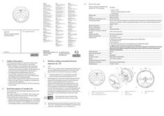
Supplementary sheet GC 173 wireless thermal detectors
Germany GEZE GmbH Niederlassung Süd-West Tel. +49 (0) 7152 203 594 E-Mail: leonberg.de@geze.com GEZE GmbH Niederlassung Süd-Ost Tel. +49 (0) 7152 203 6440 E-Mail: muenchen.de@geze.com GEZE GmbH Niederlassung Ost Tel. +49 (0) 7152 203 6840 E-Mail: berlin.de@geze.com GEZE GmbH Niederlassung Mitte/Luxemburg Tel. +49 (0) 7152 203 6888 E-Mail: frankfurt.de@geze.com GEZE GmbH Niederlassung West Tel. +49 (0) 7152 203 6770 E-Mail: duesseldorf.de@geze.com GEZE GmbH Niederlassung Nord Tel. +49 (0) 7152 203 6600 E-Mail: hamburg.de@geze.com GEZE Service GmbH Tel. +49 (0) 1802 923392 E-Mail: service-info.de@geze.com GC 173 EN Supplementary sheet Wireless ceiling-mounted thermal detector Austria GEZE Austria E-Mail: austria.at@geze.com www.geze.at Baltic States – Lithuania / Latvia / Estonia E-Mail: baltic-states@geze.com Benelux GEZE Benelux B.V. E-Mail: benelux.nl@geze.com www.geze.be www.geze.nl Bulgaria GEZE Bulgaria - Trade E-Mail: office-bulgaria@geze.com www.geze.bg China GEZE Industries (Tianjin) Co., Ltd. E-Mail: chinasales@geze.com.cn www.geze.com.cn Romania GEZE Romania S.R.L. E-Mail: office-romania@geze.com www.geze.ro GEZE Industries (Tianjin) Co., Ltd. Branch Office Shanghai E-Mail: chinasales@geze.com.cn www.geze.com.cn Russia OOO GEZE RUS E-Mail: office-russia@geze.com www.geze.ru GEZE Industries (Tianjin) Co., Ltd. Branch Office Guangzhou E-Mail: chinasales@geze.com.cn www.geze.com.cn Scandinavia – Sweden GEZE Scandinavia AB E-Mail: sverige.se@geze.com www.geze.se GEZE Industries (Tianjin) Co., Ltd. Branch Office Beijing E-Mail: chinasales@geze.com.cn www.geze.com.cn Scandinavia – Norway GEZE Scandinavia AB avd. Norge E-Mail: norge.se@geze.com www.geze.no France GEZE France S.A.R.L. E-Mail: france.fr@geze.com www.geze.fr Scandinavia – Denmark GEZE Danmark E-Mail: danmark.se@geze.com www.geze.dk Hungary GEZE Hungary Kft. E-Mail: office-hungary@geze.com www.geze.hu Singapore GEZE (Asia Pacific) Pte, Ltd. E-Mail: gezesea@geze.com.sg www.geze.com Iberia GEZE Iberia S.R.L. E-Mail: info.es@geze.com www.geze.es South Africa GEZE South Africa (Pty) Ltd. E-Mail: info@gezesa.co.za www.geze.co.za India GEZE India Private Ltd. E-Mail: office-india@geze.com www.geze.in Switzerland GEZE Schweiz AG E-Mail: schweiz.ch@geze.com www.geze.ch Italy GEZE Italia S.r.l. Unipersonale E-Mail: italia.it@geze.com www.geze.it Turkey GEZE Kapı ve Pencere Sistemleri E-Mail: office-turkey@geze.com www.geze.com GEZE Engineering Roma S.r.l E-Mail: italia.it@geze.com www.geze.it Ukraine LLC GEZE Ukraine E-Mail: office-ukraine@geze.com www.geze.ua Korea GEZE Korea Ltd. E-Mail: info.kr@geze.com www.geze.com Poland GEZE Polska Sp.z o.o. E-Mail: geze.pl@geze.com www.geze.pl 183155_01 … 2 Safety instructions To ensure personal safety, it is important to follow these safety instructions. These instructions must be kept. úú Before installation, read and observe the safety notes for these components and the drive. Warranty claims require proper mounting, installation and maintenance in accordance with the manufacturer's specifications. úú Only appropriately qualified people may carry out installation, commissioning and maintenance. Unauthorised modifications to the system release GEZE from liability for any resulting damages. úú Only use GEZE original parts for repair and service work. úú Observe the latest versions of guidelines, standards and country-specific regulations. úú Protect the components of the GC 173 from construction dirt and water. GEZE GmbH Reinhold-Vöster-Straße 21–29 71229 Leonberg Germany … Technical data Wireless ceiling-mounted thermal detector GC 173 comprising: Battery type Colour Dimensions (with base, Ø × H) Functional principle Alarm temperature EN 54-5 classification Installation position IP rating (in accordance with EN 60529) Relative humidity Ambient temperature Detector test IP20, only for dry areas 95 % (non-condensing) -10 °C to 55 °C To activate test mode: Move the test magnet near to the magnetic sensor (GEZE logo). The LED flashes green. Alarm triggering: XX United Kingdom GEZE UK Ltd. E-Mail: info.uk@geze.com www.geze.com Wireless ceiling-mounted thermal detector GC 173 Use CR 123A (3 V DC) White, RAL 9016 110 mm × 65 mm Alarm if the ambient temperature exceeds the alarm temperature or if the ambient temperature increases very quickly, no alarm saving (self-resetting as soon as the ambient temperature has dropped again) 57 °C A1R Ceiling mounting XX United Arab Emirates/GCC GEZE Middle East E-Mail: gezeme@geze.com www.geze.ae Tel.: 0049 7152 203 … Fax: 0049 7152 203 310 www.geze.com ID 195523 úú Base GC 170 B úú Wireless thermal detector GC 003 F úú Two batteries XX Move the test magnet near to the magnetic sensor (GEZE logo) again. Trigger the alarm using the heat detector testing device. The detector test using a test magnet tests the electrical components. The detector test which forms part of the regular testing of the hold-open system must be carried out using a heat detector testing device. Battery life span Signal transfer period Antenna Frequency range Range Number of frequency channels Modulation technique Radiated power The GC 173 is a wireless ceiling-mounted thermal detector for use in the GEZE hold-open system FA GC 150 or FA GC 160. Signal transfer from the detector takes place wirelessly. … years 60 s Integrated … MHz to … MHz 10 m (100 m in space) … FSK (frequency shift keying) 10 dBm / 10 mW … 1 … 5 60 … A wireless module GC 171 is essential for use of the wireless ceiling-mounted thermal detector GC 173. Thermal detectors measure the ambient temperature and respond if the temperature exceeds a certain maximum value or increases quickly within a certain time. Usually, smoke and fire gases spread quickly when a fire breaks out. It is only later that the temperature increases. As far as possible, smoke detectors should generally be used for hold-open systems. In areas where disruption such as steam, dust, condensation or operation-related smoke development (workshops, kitchens) occurs, it may, however, be sensible to use thermal detectors rather than smoke detectors. Brief description of wireless kit The wireless kit is part of the GEZE hold-open system FA GC 150 or FA GC 160. The wireless module GC 171, ID 163051, makes wireless communication possible between the lintel-mounted smoke switch and the various wireless devices. úú Wireless ceiling-mounted smoke detector GC 172 ID 195522 úú Wireless ceiling-mounted thermal detector GC 173 ID 195523 úú Wireless input module GC 175, ID 163068 (for the connection of manual trigger switches or contacts for the fire alarm system) … German institute for construction technology Smoke detectors must be used for holdopen systems for closers on rescue routes. Heed the document for the hold-open system FA GC 150 or FA GC 160 - Instructions for the installation, commissioning, operation and maintenance - see www.geze.com. … 8 … 1 … 3 Magnetic sensor for testing (behind the GEZE logo) LED for displaying state Battery compartment cover … 5 … Battery compartment Batteries Set-up switch … 8 Sabotage contact Base … Signalling State, event Switch on Start set-up of the wireless connection Fault during set-up of the wireless connection Operation Alarm Battery … discharged Battery … discharged Both batteries discharged Other faults Manipulation Loss of connection Test mode – the detector reacts sensitively to heat … LED for displaying state lights up green for … s, then repeated red flashes green until the wireless connection is established lights up red off flashes red ( … s on – … s off) flashes orange ( … s on – … s off) flashes green ( … s on – … s off) flashes orange/green alternately ( … s on – … s off) flashes orange/green alternately ( … s each) off off flashes green every second for … minute SW1x LED1x SW1x LED1x The corresponding wireless device LED1x now flashes green again for … minutes. Install batteries XX Remove the protective films from the battery compartment (4) of the new wireless detector and install the batteries (5) in the new wireless detector. Make sure of correct polarity. Battery replacement The wireless detector signals “low battery charge” to the wireless module GC 171 if the charge state of the batteries is no longer sufficient. Both batteries (5) always have to be replaced together. The set-up switch (6) for the wireless detector must not be activated. XX Take the wireless detector out of the base (8). XX Remove the battery compartment cover (3). XX Remove both batteries (5). XX Insert new batteries (type CR123A) – make sure polarity is correct. XX Replace the battery compartment cover (3). XX Insert the wireless detector into the base (8). XX Test the wireless detector. It can take up to a minute for the wireless detector to be ready for operation after battery replacement. … Set up wireless connection XX Slide a free wireless device switch SW1x of the wireless module GC 171 to the ON position. The corresponding wireless device LED1x starts to flash green. If a connection has already been set up for the wireless device switch selected, this is overwritten by the following process. The wireless module GC 171 waits for the connection query for a new wireless device. If a new wireless device does not respond within … minutes, the wireless module GC 171 cancels the connection attempt, the corresponding wireless device LED1x lights up red. XX To start the connection attempt again, slide the corresponding wireless device switch SW1x to the OFF position briefly, then slide it back into the ON position. Connecting the wireless ceiling-mounted thermal detector GC 173 to wireless module GC 171 A maximum of … wireless connections can be set up at one wireless module GC 171. The LED (2) on the new wireless ceiling-mounted detector flashes green twice first, then lights up orange for one second and then flashes red four times. As soon as the LED (2) goes out after that, the connection can be set up. … XX Slide the set-up switch (6) on the new wireless detector to the … position. After a short time, the LED of the new wireless detector will flash green for a few seconds. The corresponding wireless device LED1x of the wireless module GC 171 lights up green permanently. Pre-conditions úú All the wireless device switches of the wireless module GC 171 are in the OFF position. SW1x If the LED (2) on the new wireless detector lights up red permanently, no connection has been made. XX In this case, remove the batteries from the new wireless detector, slide the set-up switch (6) on the new wireless detector back and forward six times and install the batteries (5) again. Continue as described above. XX Fit the wireless ceiling-mounted thermal detector to the base (8). úú The set-up switch (6) of the new wireless detector is set to the ON position. Slide the wireless device switch SW1x of the wireless module GC 171 to the OFF position again. The colour the corresponding wireless device LED1x flashes indicates the quality of the wireless connection (see connection quality). XX Optimise the quality of the wireless connection if necessary by changing the position of the wireless detector. XX úú The protective films are on the battery compartment of the new wireless detector and the batteries for the new wireless detector have not been fitted. The connection of the wireless module GC 171 to the new wireless detector has been set up. XX Note the set-up connection (the number of the assigned wireless device switch) onto the identification plate of the new wireless detector. XX To set up further wireless connections, continue with step “Set up wireless connection”. Set up a new wireless connection XX Switch the supply voltage for the wireless module GC 171 on. The wireless module is in “operating” mode. XX Press the PB1 push button on the wireless module GC 171 briefly to change to the “set up wireless connection” mode. The status LED2 of the wireless module GC 171 now lights up red permanently. Press the PB1 push button on the wireless module GC 171 briefly to change to the “operating” mode. The status LED2 of the wireless module GC 171 goes off. XX PB1 PB1 SW2 SW2 GC151 GC151 GC161 GC161 24V 11 24V GND22 GND MRB 33 MRB AS 44 AS LED2 LED2 PB1 PB1 SW2 SW2 24V 11 24V GND22 GND MRB 33 MRB AS 44 AS … 2 … 4 KL1 KL1 KL1 KL1 SW1 SW1 * ** LED2 LED2 … 2 … 4 SW1 SW1 EN 54-5* EN 54-25* EN 14637** LED1 LED1 GEZE GmbH hereby declares that the components of the wireless kit for hold-open systems complies with the Directives 2014/53/EU and 2011/65/EU. The complete text of the EU Declaration of Conformity, and the Declaration of Performance, is available at the following internet address: www.geze.com GC151 GC151 GC161 GC161 LED1 LED1 German institute for construction technology EN 54-5 and EN 54-25 certified by BRE Global Ireland only with the GC171_L gateway (see document L20-GC171_-0001_REV_A.1). EN 14637 certified by KRIWAN with GC 172, GC 173, GC 175 and GC171 gateway.
PDF | 2 MB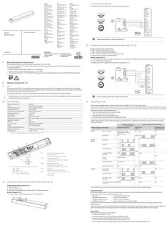
GC 171 wireless module
Singapore GEZE (Asia Pacific) Pte, Ltd. E-Mail: gezesea@geze.com.sg www.geze.com Iberia GEZE Iberia S.R.L. E-Mail: info.es@geze.com www.geze.es South Africa GEZE South Africa (Pty) Ltd. E-Mail: info@gezesa.co.za www.geze.co.za India GEZE India Private Ltd. E-Mail: office-india@geze.com www.geze.in Switzerland GEZE Schweiz AG E-Mail: schweiz.ch@geze.com www.geze.ch Italy GEZE Italia S.r.l. Unipersonale E-Mail: italia.it@geze.com www.geze.it Turkey GEZE Kapı ve Pencere Sistemleri E-Mail: office-turkey@geze.com www.geze.com GEZE Engineering Roma S.r.l E-Mail: italia.it@geze.com www.geze.it Ukraine LLC GEZE Ukraine E-Mail: office-ukraine@geze.com www.geze.ua Korea GEZE Korea Ltd. E-Mail: info.kr@geze.com www.geze.com Connection to the lintel-mounted smoke switch GC 161 Tel.: 0049 7152 203 … Fax: 0049 7152 203 310 www.geze.com Fun GC kmod 171 ul Fun mo keinga d be GC1 ul 75 Fes t vor stellr 1- ichtu g . / … ng - g Use Han dau l ö s e tast ser Wireless module GC 171 Stu r Aus zmeld löse er m vo it r r i cht ung Brief description of wireless kit The wireless kit is part of the GEZE hold-open system FA GC 150 or FA GC 160. The wireless module GC 171, ID 163051, makes wireless communication possible between the lintel-mounted smoke switch and the various wireless devices. àà Wireless ceiling-mounted smoke detector GC 172, ID 159656 àà Wireless ceiling-mounted thermal detector GC 173, ID 159657 àà Wireless input module GC 175, ID 163068 (for the connection of manual trigger switches or contacts for the fire detector system) Fun dec kme kenlde r Wireless module GC 171: XX The housing of the wireless module must be at least … cm away from the smoke intake openings of the lintel-mounted smoke switch. XX Set switch SW2 to the OFF position. Use cable type J-Y(ST)Y, 2x2x0.6 mm or 2x2x0.8 mm. Length max. … m. The wireless module GC 171 is connected to the lintel-mounted smoke switch. An alarm triggered at a wireless module is indicated immediately at the lintel-mounted smoke switch. Interference with a wireless device or a problem with communication is indicated on the lintel-mounted smoke switch in less than 100 ms. The wireless module GC 171 forwards wireless signals to the lintel-mounted smoke switch as changes in resistance. ON OFF Heed the document for the hold-open system FA GC 150 or FA GC 160 - Instructions for the installation, commissioning, operation and maintenance, see www.geze.com. … Technical data * On GC 161 always set DIP switch … to DIP switch … to ON. … Wireless module GC 171 Colour Dimensions (W x H x D) Installation position IP rating (in acc. with EN 60529) Ambient temperature Input voltage Input current Number of wireless participants Signal transfer period Antenna Frequency range Range Number of frequency channels Modulation technique Radiated power ID 163051 RAL 7016 (anthracite grey) 177 mm x 30 mm x 18 mm Wall assembly IP20, only for dry areas -5°C to 50°C 24 V DC * Maximum of 15 mA * The wireless module GC 171 can communicate with a maximum of … wireless devices. 60 s integrated … MHz to … MHz 10 m (100 m in space) … FSK (frequency shift keying) 10 dBm / 10 mW inte gri e r t eF Rau est ch e l s l c a h nla a ltze ge Ene ntr a l e v rgie e RSZ r sor … gun g Lintel-mounted smoke switch GC 161: XX DIP1 = ON (with manual trigger switch) XX DIP2 = ON (with ceiling-mounted detector) XX DIP3 = ON (line monitoring to the manual trigger switch) XX Connect KL2.9 to KL2.10 via a … kΩ resistor Fun mo keinga d be GC1 ul 75 … Han löse daustast er … Always remove jumpers J1 and J2 from the GC 151. Fun dec kme kenlde r … GEZE GmbH Reinhold-Vöster-Straße 21–29 71229 Leonberg Germany J2 J1 Han lö dau s e tast ser 183119-02 United Kingdom GEZE UK Ltd. E-Mail: info.uk@geze.com www.geze.com J3 Han lö dau s e tast ser Poland GEZE Polska Sp.z o.o. E-Mail: geze.pl@geze.com www.geze.pl United Arab Emirates/GCC GEZE Middle East E-Mail: gezeme@geze.com www.geze.ae est e l l a nla ge ntr a l e RSZ … Hungary GEZE Hungary Kft. E-Mail: office-hungary@geze.com www.geze.hu Stu r Aus zmeld löse er m vo it r r i ch t ung Scandinavia – Denmark GEZE Danmark E-Mail: danmark.se@geze.com www.geze.dk Fes t vor stellr 1- i c h t u g . / … ng - g France GEZE France S.A.R.L. E-Mail: france.fr@geze.com www.geze.fr Fun GC kmod 171 ul Scandinavia – Norway GEZE Scandinavia AB avd. Norge E-Mail: norge.se@geze.com www.geze.no Dec me kenlde r GEZE Industries (Tianjin) Co., Ltd. Branch Office Beijing E-Mail: chinasales@geze.com.cn www.geze.com.cn Dec me kenlde r Bulgaria GEZE Bulgaria - Trade E-Mail: office-bulgaria@geze.com www.geze.bg Scandinavia – Sweden GEZE Scandinavia AB E-Mail: sverige.se@geze.com www.geze.se Fun dec km e k en ld e r Benelux GEZE Benelux B.V. E-Mail: benelux.nl@geze.com www.geze.be www.geze.nl GEZE Industries (Tianjin) Co., Ltd. Branch Office Guangzhou E-Mail: chinasales@geze.com.cn www.geze.com.cn Use cable type J-Y(ST)Y, 2x2x0.6 mm or 2x2x0.8 mm. Length max. … m. Fun mo keinga d be GC1 ul 75 Wireless module Russia OOO GEZE RUS E-Mail: office-russia@geze.com www.geze.ru Set switch SW2 to the ON position. Han dau l ö s e tast ser Baltic States – Lithuania / Latvia / Estonia E-Mail: baltic-states@geze.com GEZE Industries (Tianjin) Co., Ltd. Branch Office Shanghai E-Mail: chinasales@geze.com.cn www.geze.com.cn XX Fu n dec kk e el d n er EN Supplementary sheet GC 171 Romania GEZE Romania S.R.L. E-Mail: office-romania@geze.com www.geze.ro Fun mo keinga d be GC1 ul 75 Austria GEZE Austria E-Mail: austria.at@geze.com www.geze.at China GEZE Industries (Tianjin) Co., Ltd. E-Mail: chinasales@geze.com.cn www.geze.com.cn Han löse daustast er Germany GEZE GmbH Niederlassung Süd-West Tel. +49 (0) 7152 203 594 E-Mail: leonberg.de@geze.com GEZE GmbH Niederlassung Süd-Ost Tel. +49 (0) 7152 203 6440 E-Mail: muenchen.de@geze.com GEZE GmbH Niederlassung Ost Tel. +49 (0) 7152 203 6840 E-Mail: berlin.de@geze.com GEZE GmbH Niederlassung Mitte/Luxemburg Tel. +49 (0) 7152 203 6888 E-Mail: frankfurt.de@geze.com GEZE GmbH Niederlassung West Tel. +49 (0) 7152 203 6770 E-Mail: duesseldorf.de@geze.com GEZE GmbH Niederlassung Nord Tel. +49 (0) 7152 203 6600 E-Mail: hamburg.de@geze.com GEZE Service GmbH Tel. +49 (0) 1802 923392 E-Mail: service-info.de@geze.com “Operating” mode After the supply voltage has been switched on, the wireless module GC 171 is in “operating” mode. In “operating” mode the wireless module monitors the set-up wireless connections and signals faults and alarms to the lintel-mounted smoke switch. Faults and alarms are also indicated on the status LED and the wireless device LEDs of the wireless module. The following table shows the states for the different events: àà of the wireless device LEDs of the wireless module, àà of the status LED of the wireless module, àà of the LED of the lintel-mounted smoke switch, àà of the hold-open output of the lintel-mounted smoke switch. The wireless module indicates an event until the cause has been eliminated. If the cause of an event is no longer present, the wireless module changes back to normal mode (the displays are deleted and 24 V is applied to the hold-open output of the lintel-mounted smoke switch again). Wireless module GC 171 (“operating” mode) Lintel-mounted smoke switch GC 151 Wireless connection State / fault Wireless device LED 1x Status LED1) LED Hold-open output KL1: 3-4 / KL3: 1-2 GC 171 green flashes good yellow flashes sufficient red flashes poor off off 24 V Connection quality The GC 171 will be supplied from a limited power source (LPS). General fault green yellow red 0V off PB1 GC 172 GC 173 SW2 GC151 GC161 24V … GND … PB1 MRB … AS … LED2 LED2 PB1 SW2 GC161 SW2 SW2GC151 LED2 KL1 SW1 LED1 … GC151 GC161 LED2 … KL1 LED11...LED16 LED1 LED11...LED16SW11...SW16 LED11...LED16 SW1 SW1 SW11...SW16 LED1 SW11...SW16 KL1 KL1AS KL1 KL1 red Sabotage off red Loss of connection off red LED2 LED2 SW2 SW2 24V GND MRB … 24V … AS … GND … MRB … 4 ASKL1 General fault theAS ASlintel-mounted Connection to smoke switch 24 V Supply GND Supply MRB Manual trigger switch AS Ceiling-mounted detector PB1 Push button for mode selection “Operating” mode “Set up wireless connection” mode LED1x Wireless device-LEDs … LEDs, one LED belongs to one specific wireless device. SW1x Wireless device switch … sliding switches, one switch belongs to one specific wireless device. LED2 Status LED Indicates the status of the GC 171. SW2 Selection of the lintel-mounted smoke switch OFF = GC 161 ON = GC 151. Low battery charge (warning) Soiling (warning) GC 175 red/green long Wireless detector alarm red General fault, broken cable Loss of connection Connection to the lintel-mounted smoke switch GC 151 Lintel-mounted smoke switch GC 151: XX Remove jumper J1. XX Remove jumper J2 (red). XX Set jumper J3 to the measuring chamber (PIN 2-3 with line monitoring). Wireless module GC 171: àà The area defined in the following illustration must be kept free. 30 30 … 5 off green 24 V red red off red red off red off Contact (N/O contact) activated, yellow short-circuit 0V 0V red off yellow 0V yellow off red/green briefly Soiling limit reached Low battery charge (warning) … off yellow red off yellow green 24 V yellow 0V 1) If the LED flashes red … x on the lintel-mounted smoke switch GC 161, the … kΩ resistor has not been connected properly. Connection quality If the wireless device switch is in the OFF position during “operating” mode, the corresponding wireless device LED indicates the connection quality to the corresponding wireless device: àà LED is off g no wireless connection set up àà LED flashes green every … s g good connection quality àà LED flashes yellow every … s g sufficient connection quality àà LED flashes red every … s g still connected but poor connection quality Connection interference is possible, the quality of the wireless connection should be optimised by changing the position of the wireless device. If the wireless device switch is in the OFF position in “operating” mode and the wireless device signals an event (a warning, a fault or an alarm), the wireless device LED indicates this event in compliance with the table above instead of the connection quality. General fault The wireless module signals “general fault” if àà no wireless connection is set up, àà the wireless module is in the “set up wireless connection” mode, àà the set-up switch is in the ON position with GC 172, GC 173 or GC 175, àà an internal fault has occurred during smoke detection with GC 172 àà the connection between the wireless input module and termination resistor is interrupted with GC 175. Sabotage The wireless module signals “sabotage” if a wireless detector GC 172 or GC 173 has been removed from its base. Loss of connection If the wireless module does not receive a new message from a set-up wireless device within 100 s of the last message, the wireless module signals “loss of connection” for the corresponding wireless connection. The wireless module continues to monitor this wireless connection. If the wireless module sends a signal again in time, the wireless module returns to “normal operation”. Low battery charge The wireless module signals “low battery charge” if the voltage of the main battery of the corresponding wireless device falls to less than … V. Both batteries (main battery and slave battery) must be replaced. Soiling The wireless module signals “soiling” if the inside of the smoke chamber of the wireless smoke detector GC 172 is heavily soiled. The corresponding wireless smoke detector should be replaced. Soiling limit reached The wireless module signals “soiling limit reached” if the inside of the smoke chamber of the wireless smoke detector GC 172 is too heavily soiled. The wireless smoke detector must be replaced. Wireless detector alarm The wireless module signals “wireless ceiling-mounted detector alarm” if the wireless smoke detector GC 172 or the wireless thermal detector GC 173 triggers. The signal is acknowledged automatically when the cause of the alarm is no longer present. The wireless module returns to “normal operation”. Contact activated The wireless module signals “contact activated” if the input of the wireless input module GC 175 is short-circuited (when the connected contact is closed or in the event of short-circuit of the connection to the contact). The signal is acknowledged automatically when the short-circuit is no longer present. The wireless module returns to “normal operation”. Event memory The wireless module saves the last event for every connected wireless device. A new event overwrites the last event. In order to check whether an event has been saved for the wireless device, slide the corresponding wireless device switch to the ON position. If an event has been saved for this wireless device, the corresponding wireless device LED will then display this event as shown in the table above. If the wireless device LED is green, then no event has been saved for this wireless device. When the wireless device switch is slid back to the OFF position, any event saved is deleted. … Set up wireless connection” mode In the “set up wireless connection” mode, new wireless connections can be set up to new wireless devices GC 172, GC 173 or GC 175. A maximum of … wireless connections can be set up. If the LED on the new wireless device lights up red permanently, no connection has been made. XX In this case, remove the main battery from the new wireless device, slide the set-up switch on the new wireless device back and forward six times and start again with “Install batteries”. XX Fit the wireless ceiling-mounted detector to the base and close the housing of the wireless input module. XX Slide the wireless device switch SW1x of the wireless module GC 171 to the OFF position again. The colour of the flashing of the corresponding wireless device LED1x ndicates the quality of the wireless connection (see chap. … .1). XX Optimise the quality of the wireless connection if necessary by changing the position of the wireless device. The connection of the wireless module GC 171 to the new wireless device has been set up. XX Note the set-up connection (number of the assigned wireless device switch) on the new wireless device unit e.g. on its identification plate. XX To set up further wireless connections, continue with step “Set up wireless connection”. XX Press the PB1 push button on the wireless module GC 171 briefly to change to the “operating” mode. The status LED2 of the wireless module GC 171 goes off. After the supply voltage has been switched on, the wireless module GC 171 is in “operating” mode. All the wireless device switches SW1x are in the OFF position. Press the PB1 push button briefly to change to the “set up wireless connection” mode. The status LED2 of the wireless module is now permanently lit red. XX Slide a free wireless device switch SW1x of the wireless module GC 171 to the ON position. If a connection has already been set up for the wireless device switch selected, this is overwritten by the following process. The corresponding wireless device LED1x starts to flash green. The wireless module GC 171 waits for the connection query for a new wireless device. If a wireless device does not respond within … minutes, the GC 171 cancels the connection attempt, the corresponding wireless device LED1x lights up red. XX To start the connection attempt again, slide the corresponding wireless device switch SW1x to the OFF position briefly, then slide it back into the ON position. The corresponding wireless device LED1x flashes green again for … minutes. PB1 PB1 SW2 SW2 GC151 GC151 GC161 GC161 KL1 KL1 SW1 SW1 LED2 LED2 LED1 LED1 SW1x LED1x Remove the protective film from the battery compartment of the new wireless device and install the main battery in the new wireless device (ensure correct polarity). Wireless ceiling-mounted detector GC 172 or GC 173: The LED of the new wireless ceiling-mounted detector flashes green twice first, then lights up yellow for one second and then flashes red four times. As soon as the LED goes out after that, the connection can be set up. Wireless input module GC 175: The LED of the new wireless input module flashes green once first, then lights up yellow for one second and then flashes red four times. As soon as the LED goes out after that, the connection can be set up. XX Slide the set-up switch on the new wireless device to the … position. After a short time, the LED of the new wireless device will flash green for a few seconds. The corresponding wireless device LED1x of the wireless module GC 171 lights up green permanently. PB1 PB1 SW2 SW2 GC151 GC151 GC161 GC161 Slide all … wireless device switches SW1x to the ON position. The wireless device LED1x light up yellow in succession until all the wireless device switches are in the ON position. They then flash red for … s. Within these … s, deletion of the wireless connections can be cancelled by sliding one or more wireless device switches back to the OFF position KL1 KL1 Press the PB1 push button briefly to change back to the “operating” mode. The status LED2 of the wireless module is now permanently lit yellow. SW1 SW1 LED2 LED2 LED1 LED1 SW1x LED1x SW1x PB1 PB1 SW2 SW2 GC151 GC151 GC161 GC161 KL1 KL1 Install batteries XX LED1 LED1 LED2 LED2 24V 11 24V GND22 GND MRB 33 MRB AS 44 AS 24V 11 24V GND22 GND MRB 33 MRB AS 44 AS XX SW1 SW1 SW1x Now all … wireless device LED1x are lit yellow permanently, all wireless connections are deleted XX Slide all … wireless device switches SW1x back to the OFF position. After the supply voltage has been switched on, the wireless module GC 171 is in “operating” mode. Set up wireless connection LED2 LED2 24V 11 24V GND22 GND MRB 33 MRB AS 44 AS SW1x àà The protective film is on the battery compartment of the new wireless device and the main battery for the new wireless device has not been fitted. GC151 GC151 GC161 GC161 Delete all wireless connections All wireless connections already set up can be deleted in the “set up wireless connection” mode. XX Press the PB1 push button on the wireless module GC 171 briefly to change to the “set up wireless connection” mode. The status LED2 of the wireless module GC 171 is now permanently lit red. SW2 SW2 KL1 KL1 XX àà The set-up switch of the new wireless device is set to the ON position. XX PB1 PB1 LED1x 24V 11 24V GND22 GND MRB 33 MRB AS 44 AS Pre-conditions àà All the wireless device switches of the wireless module GC 171 are in the OFF position. SW1x ON SW1 SW1 LED1 LED1 EN 54-18 EN 54-25 EN 14637
PDF | 4 MB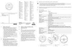
Supplementary sheet GC 172 wireless ceiling-mounted smoke detector
Germany GEZE GmbH Niederlassung Süd-West Tel. +49 (0) 7152 203 594 E-Mail: leonberg.de@geze.com GEZE GmbH Niederlassung Süd-Ost Tel. +49 (0) 7152 203 6440 E-Mail: muenchen.de@geze.com GEZE GmbH Niederlassung Ost Tel. +49 (0) 7152 203 6840 E-Mail: berlin.de@geze.com GEZE GmbH Niederlassung Mitte/Luxemburg Tel. +49 (0) 7152 203 6888 E-Mail: frankfurt.de@geze.com GEZE GmbH Niederlassung West Tel. +49 (0) 7152 203 6770 E-Mail: duesseldorf.de@geze.com GEZE GmbH Niederlassung Nord Tel. +49 (0) 7152 203 6600 E-Mail: hamburg.de@geze.com GEZE Service GmbH Tel. +49 (0) 1802 923392 E-Mail: service-info.de@geze.com GC 172 EN Supplementary sheet Wireless ceiling-mounted smoke detector Austria GEZE Austria E-Mail: austria.at@geze.com www.geze.at Baltic States – Lithuania / Latvia / Estonia E-Mail: baltic-states@geze.com Benelux GEZE Benelux B.V. E-Mail: benelux.nl@geze.com www.geze.be www.geze.nl Bulgaria GEZE Bulgaria - Trade E-Mail: office-bulgaria@geze.com www.geze.bg China GEZE Industries (Tianjin) Co., Ltd. E-Mail: chinasales@geze.com.cn www.geze.com.cn Romania GEZE Romania S.R.L. E-Mail: office-romania@geze.com www.geze.ro GEZE Industries (Tianjin) Co., Ltd. Branch Office Shanghai E-Mail: chinasales@geze.com.cn www.geze.com.cn Russia OOO GEZE RUS E-Mail: office-russia@geze.com www.geze.ru GEZE Industries (Tianjin) Co., Ltd. Branch Office Guangzhou E-Mail: chinasales@geze.com.cn www.geze.com.cn Scandinavia – Sweden GEZE Scandinavia AB E-Mail: sverige.se@geze.com www.geze.se GEZE Industries (Tianjin) Co., Ltd. Branch Office Beijing E-Mail: chinasales@geze.com.cn www.geze.com.cn Scandinavia – Norway GEZE Scandinavia AB avd. Norge E-Mail: norge.se@geze.com www.geze.no France GEZE France S.A.R.L. E-Mail: france.fr@geze.com www.geze.fr Scandinavia – Denmark GEZE Danmark E-Mail: danmark.se@geze.com www.geze.dk Hungary GEZE Hungary Kft. E-Mail: office-hungary@geze.com www.geze.hu Singapore GEZE (Asia Pacific) Pte, Ltd. E-Mail: gezesea@geze.com.sg www.geze.com Iberia GEZE Iberia S.R.L. E-Mail: info.es@geze.com www.geze.es South Africa GEZE South Africa (Pty) Ltd. E-Mail: info@gezesa.co.za www.geze.co.za India GEZE India Private Ltd. E-Mail: office-india@geze.com www.geze.in Switzerland GEZE Schweiz AG E-Mail: schweiz.ch@geze.com www.geze.ch Italy GEZE Italia S.r.l. Unipersonale E-Mail: italia.it@geze.com www.geze.it Turkey GEZE Kapı ve Pencere Sistemleri E-Mail: office-turkey@geze.com www.geze.com GEZE Engineering Roma S.r.l E-Mail: italia.it@geze.com www.geze.it Ukraine LLC GEZE Ukraine E-Mail: office-ukraine@geze.com www.geze.ua Korea GEZE Korea Ltd. E-Mail: info.kr@geze.com www.geze.com Poland GEZE Polska Sp.z o.o. E-Mail: geze.pl@geze.com www.geze.pl 183121_01 GEZE GmbH Reinhold-Vöster-Straße 21–29 71229 Leonberg Germany United Arab Emirates/GCC GEZE Middle East E-Mail: gezeme@geze.com www.geze.ae United Kingdom GEZE UK Ltd. E-Mail: info.uk@geze.com www.geze.com Tel.: 0049 7152 203 … Fax: 0049 7152 203 310 www.geze.com … Protection of the smoke detector from contamination úú Do not remove the dust protection cap from the smoke detector until commissioning is about to take place. úú After the smoke detector has been installed and the dust protection removed, make sure no dust gets into the measuring chamber. This leads to increased contamination and can significantly shorten the service life of the smoke detector. úú The measuring chamber of a smoke detector must not be opened. Heed the document for the hold-open system FA GC 150 or FA GC 160 - Instructions for the installation, commissioning, operation and maintenance, see www.geze.com. … Technical data Wireless ceiling-mounted smoke detector GC 172 comprising: ID 195522 úú Base GC 170 B úú Wireless smoke detector GC 002 F úú Two batteries Battery type Colour Dimensions (with base, Ø × H) CR 123A (3 V DC) White, RAL 9016 110 mm × 65 mm Scatter light, adaption of the alarm threshold, no alarm saving (self-resetting as soon as there is Functional principle no more smoke in the measuring chamber) Insect grid Prevents insects getting into the measuring chamber Installation position Ceiling mounting IP rating (in accordance with EN 60529) IP20, only for dry areas Relative humidity 95% (non-condensing) Ambient temperature -10 °C to 55 °C To activate test mode: Detector test XX Move the test magnet near to the magnetic sensor (GEZE logo). The LED flashes green. Alarm triggering: XX XX … 2 Safety instructions To ensure personal safety, it is important to follow these safety instructions. These instructions must be kept. úú Before installation, read and observe the safety notes for these components and the drive. Warranty claims require proper mounting, installation and maintenance in accordance with the manufacturer's specifications. úú Only appropriately qualified people may carry out installation, commissioning and maintenance. Unauthorised modifications to the system release GEZE from liability for any resulting damages. úú Only use GEZE original parts for repair and service work. úú Observe the latest versions of guidelines, standards and country-specific regulations. úú Protect the components of the GC 172 from construction dirt and water. Brief description of wireless kit The wireless kit is part of the GEZE hold-open system FA GC 150 or FA GC 160. The wireless module GC 171, ID 163051, makes wireless communication possible between the lintel-mounted smoke switch and the various wireless devices: úú Wireless ceiling-mounted smoke detector GC 172 ID 195522 úú Wireless ceiling-mounted thermal detector GC 173 ID 195523 úú Wireless input module GC 175, ID 163068 (for the connection of manual trigger switches or contacts for the fire alarm system) … Wireless ceiling-mounted smoke detector GC 172 Use The GC 172 is a wireless ceiling-mounted smoke detector for use in the GEZE hold-open system FA GC 150 or FA GC 160. Signal transfer from the detector takes place wirelessly. A wireless module GC 171 is essential for use of the wireless ceiling-mounted smoke detector GC 172. Move the test magnet near to the magnetic sensor (GEZE logo) again. Trigger the alarm using the test aerosol. The detector test using a test magnet tests the electrical components. The detector test which forms part of the regular testing of the hold-open system must be carried out using a test aerosol Battery life span Signal transfer period Antenna Frequency range Range Number of frequency channels Modulation technique Radiated power Smoke detectors detect smoke. They work using the scattered light principle. A light transmitter and a light interface are arranged in the measuring chamber in such a way that no light reaches the interface in the normal case. If there are suspended particles (smoke) in the measuring chamber, these scatter part of the light onto the interface, which converts this into an electric signal. In other words, a smoke detector not only detects smoke but all other suspended particles and responds sensitively to contamination. … years 60 s Integrated … MHz to … MHz 10 m (100 m in space) … FSK (frequency shift keying) 10 dBm / 10 mW … 1 … 5 60 … 7 … 2 … 2 … Magnetic sensor for testing (behind the GEZE logo) LED for displaying state Battery compartment cover … 5 … Battery compartment Batteries Set-up switch … 8 Sabotage contact Base … State, event Switch on Start set-up of the wireless connection Fault during set-up of the wireless connection Operation Alarm Battery … discharged Battery … discharged Both batteries discharged Other faults Manipulation Loss of connection Test mode – the detector reacts sensitively to aerosol pulses … Set up wireless connection Signalling LED for displaying state lights up green for … s, then repeated red flashes green until the wireless connection is established lights up red off flashes red ( … s on – … s off) flashes orange ( … s on – … s off) flashes green ( … s on – … s off) flashes orange/green alternately ( … s on – … s off) flashes orange/green alternately ( … s each) off off flashes green every second for … minute SW1x LED1x SW1x LED1x Install batteries XX Remove the protective films from the battery compartment (4) of the new wireless detector and install the batteries (5) in the new wireless detector. Make sure of correct polarity. Battery replacement The wireless detector signals “low battery charge” to the wireless module GC 171 if the charge state of the batteries is no longer sufficient. Both batteries (5) always have to be replaced together. The set-up switch (6) for the wireless detector must not be activated. XX Take the wireless detector out of the base (8). XX Remove the battery compartment cover (3). XX Remove both batteries (5). XX Insert new batteries (type CR123A) – make sure polarity is correct. XX Replace the battery compartment cover (3). XX Insert the wireless detector into the base (8). XX Test the wireless detector. It can take up to a minute for the wireless detector to be ready for operation after battery replacement. … XX Slide a free wireless device switch SW1x of the wireless module GC 171 to the ON position. The corresponding wireless device LED1x starts to flash green. If a connection has already been set up for the wireless device switch selected, this is overwritten by the following process. The wireless module GC 171 waits for the connection query for a new wireless device. If a new wireless device does not respond within … minutes, the wireless module GC 171 cancels the connection attempt, the corresponding wireless device LED1x lights up red. XX To start the connection attempt again, slide the corresponding wireless device switch SW1x to the OFF position briefly, then slide it back into the ON position. The corresponding wireless device LED1x now flashes green again for … minutes. Connecting the wireless ceiling-mounted smoke detector GC 172 to wireless module GC 171 A maximum of … wireless connections can be set up at one wireless module GC 171. The LED (2) on the new wireless ceiling-mounted detector flashes green twice first, then lights up orange for one second and then flashes red four times. As soon as the LED (2) goes out after that, the connection can be set up. … XX Slide the set-up switch (6) on the new wireless detector to the … position. After a short time, the LED of the new wireless detector will flash green for a few seconds. The corresponding wireless device LED1x of the wireless module GC 171 lights up green permanently. Pre-conditions úú All the wireless device switches of the wireless module GC 171 are in the OFF position. SW1x If the LED (2) on the new wireless detector lights up red permanently, no connection has been made. XX In this case, remove the batteries from the new wireless detector, slide the set-up switch (6) on the new wireless detector back and forward six times and install the batteries (5) again. Continue as described above. XX Fit the wireless ceiling-mounted smoke detector to the base (8). úú The set-up switch (6) of the new wireless detector is set to the ON position. Slide the wireless device switch SW1x of the wireless module GC 171 to the OFF position again. The colour the corresponding wireless device LED1x flashes indicates the quality of the wireless connection (see connection quality). XX Optimise the quality of the wireless connection if necessary by changing the position of the wireless detector. XX The connection of the wireless module GC 171 to the new wireless detector has been set up. úú The protective films are on the battery compartment of the new wireless detector and the batteries for the new wireless detector have not been fitted. XX XX Set up a new wireless connection Press the PB1 push button on the wireless module GC 171 briefly to change to the “operating” mode. The status LED2 of the wireless module GC 171 goes off. XX Switch the supply voltage for the wireless module GC 171 on. The wireless module is in “operating” mode. XX XX Press the PB1 push button on the wireless module GC 171 briefly to change to the “set up wireless connection” mode. The status LED2 of the wireless module GC 171 now lights up red permanently. Note the set-up connection (the number of the assigned wireless device switch) onto the identification plate of the new wireless detector. To set up further wireless connections, continue with step “Set up wireless connection”. PB1 PB1 SW2 SW2 GC151 GC151 GC161 GC161 24V 11 24V GND22 GND MRB 33 MRB AS 44 AS KL1 KL1 PB1 PB1 SW2 SW2 24V 11 24V GND22 GND MRB MRB 33 AS 44 AS LED2 LED2 … 2 … 4 KL1 KL1 SW1 SW1 LED2 LED2 … 2 … 4 SW1 SW1 LED1 LED1 EN 54-7* EN 54-25* EN 14637** LED1 LED1 GEZE GmbH hereby declares that the components of the wireless kit for hold-open systems complies with the Directives 2014/53/EU and 2011/65/EU. The complete text of the EU Declaration of Conformity, and the Declaration of Performance, is available at the following internet address: www.geze.com GC151 GC151 GC161 GC161 * ** EN 54-7 and EN 54-25 certified by BRE Global Ireland only with the GC171_L gateway (see document L20-GC171_-0001_REV_A.1). EN 14637 certified by KRIWAN with GC 172, GC 173, GC 175 and GC171 gateway.
PDF | 2 MB